

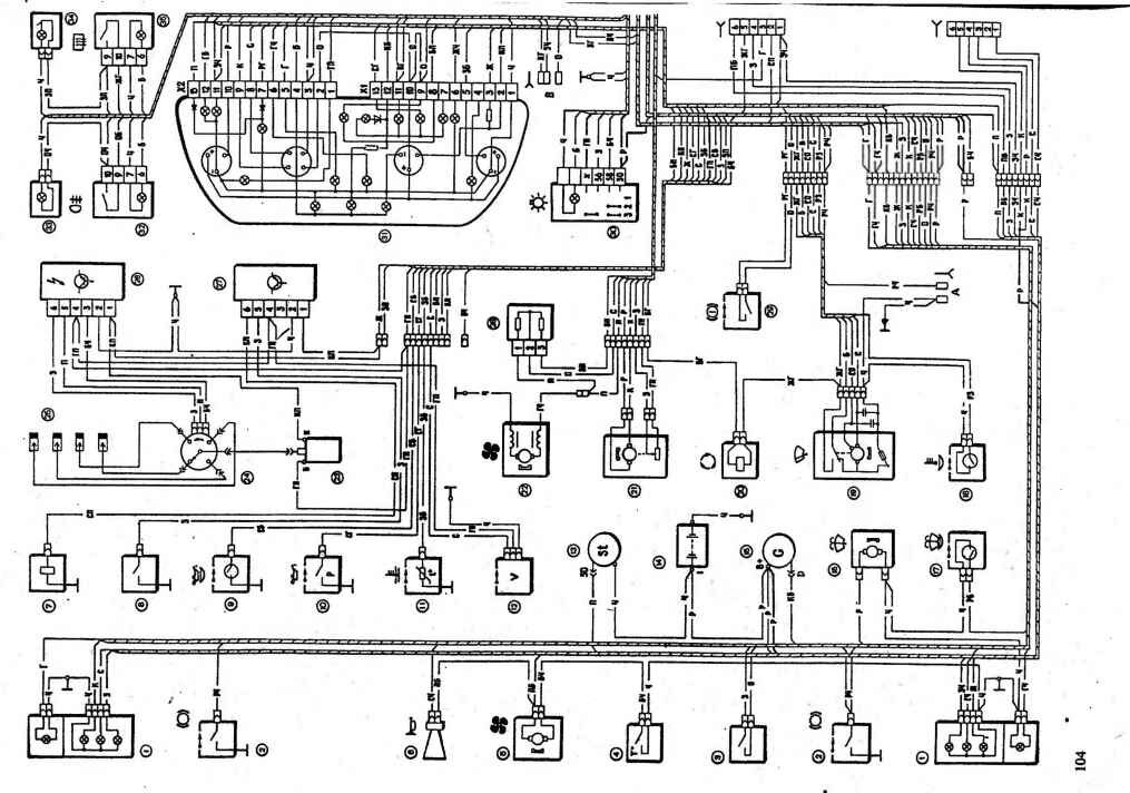
The electrical equipment on a single scheme-the negative conclusions of sources and electricity consumers are connected to the car body, which acts as the second wire; Driving the vehicle`s electrical shown in Fig. 7-1.
Most of the electrical items work when the ignition switch. Regardless of the ignition switch work: alarm-beam assistant, watches, brake light, Outdoor lighting, Courtesy light and individual lighting, alarm, horn, electric cooling fan motor and sockets for a portable lamp.
Most of the vehicle`s electrical power circuits are protected by fuses. Not fused circuit the battery charge, the ignition circuit and the starter motor generator with the exception of the field winding.
Before replacing a blown fuse, find out the cause of the combustion and eliminate it. When troubleshooting, it is recommended to see specified in Table 7-1 chain that protects the fuse.
Table 7-1
circuits protected by fuses
|
№ Fuse |
Protected chain |
|
5 A P1 |
lamps license plate light. Lamps lighting devices. The control lamp of dimensional light. The lamp lighting the trunk. Lamps gabaritnogosvetalevogo board |
|
HS 7.5 A |
The left headlight of a passing light. |
|
RZYUA |
The left headlight main beam. |
|
R410A |
rules against votumannaya spotlight. |
|
A 30 B5 |
Electric windows doors. |
|
A 15 B6 |
Hand lamp. |
|
R720A |
The electric cooling fan motor. Beep. |
|
R820A |
Heated rear screen. The relay contacts switching heated rear window. |
|
A 1 = 920 |
recirculation valve. windscreen wipers and washers, rear The glass and headlights. The relay coil switching heated rear window. |
|
R1020A |
Reserve. |
|
& yen; 11 5 amps |
Lamps starboard side light. |
|
& yen; P 7,5 A |
The right headlight of a passing light. |
|
R1310A |
Right spotlight. The control lamp of inclusion of headlights. |
|
A 10 B14 |
The left proti votumannaya spotlight. |
|
R1520A |
Heated seats. Locking the trunk lock. |
|
A 10 B16 |
The relay-breaker indicators and alarms in alarm mode. Control lampaavariynoy alarm. |
|
P17 7.5A |
room lamp. The lamp illumination individual. The lamp in the ignition switch. Lamps stoplight. Watch and trip computer. |
|
25 A, B18 |
glove compartment light. Heater controller. Cigarette lighter |
|
A 10 B19 |
door lock. Relay control lamp serviceability stoplight and marker light. Pointers povrrotaskontreshnymi lamps. Lamps light backing. The winding of the generator. Blokindikatsii-board control system. A combination of devices. Clock or trip computer. |
|
A G20 7.5 |
Rear Lamps proti votu Mann`s lights. |
cassocks. 7 -1. Diagram of electrical cars VAZ-2110: 1-the lens unit; 2-wear indicator of the front brakes; 3-the switch of light of a backing; 4-the gauge of inclusion of the fan motor; 5-the motor cooling fan motor; 6-horn; 7-solenoid valve carburetor; 8-the limit switch the carburetor; 9-the gauge of the index of oil; 10-the gauge of a control lamp of pressure of oil; 11-sensor coolant temperature; 12-speed sensor; 13-starter; 14-the storage battery; 15-the generator; 16-AC washer vetrvogo glass; І7-washer fluid level sensor; 18-liquid level sensor ohllazhdayuschey; 19-motoreduktor windscreen wiper; 20-recirculation valve; 21-mikromotoreduktor door actuator heater; 22-electric heater; 23-the ignition coil; 24-the gauge-distributor; 25-a spark plug; 26-the switch; 27-control solenoid valve carburetor; 28-additional resistor electric heater; 29-the brake fluid level; 30-switch outdoor lighting; 31-a combination of devices; 32-switch fog lights; 33-a control lamp fog light; 34-a control lamp heated rear window; 35-the switch of heating of back glass;-36-column switch; 37-the switch of lighting devices; 38-the ignition switch; 39-mounting unit; 40-the gauge of the index of level of fuel; 41-the switch of the EGR valve; 42-socket for portable lamps; 43-heater controller; 44-display unit board control system; 45-switch the alarm; 46-hours; 47-a lamp lighting the heater control levers; 48-the glove compartment light; 51-vyklyuchetel the parking brake; 52-cigarette lighter; 53-the gauge of the driver seat belt; 54-Light Ashtray; 55-the switch of a stoplight; 56-individual ceiling interior lighting; 57-Courtesy light; 58-the temperature sensor for the heating system; 59-switches in racks front doors; 60-switches in the rack rear doors; 61-external taillights; 62-inner taillights; 63-Number plate lights; 64-the luggage compartment lamp; K1-Relay control lamp serviceability; K2-the relay windscreen wiper; RS-relay-breaker indicators and alarms; K4-relay dipped beam; K5-the relay of inclusion of headlights; KB-additional relay; K7-relay switching heated rear window; K8-relay back on cars VAZ-2110 is not installed. A-pads for connecting the motor rear window washer; B-to harness gfedupreditelnogo block light; C -block for connection to the on-board computer; TU-to the harness pad cleaner headlights; E-to the rear screen; B-block for connection of an additional signal of braking. The diagram is not shown, in the instrument panel harness second ends of all wires of white, black, orange, white with red and yellow stripe with blue stripe interconnected with certain points
In Table. 7-1 given to the purpose of each fuse, but in particular modeli4 vehicle may not have all the circuit or device, shown in the table.
In all the diagrams in the "Electrical" wire colors designated by the letters, the first letter-the color of the wire, and the second-the color of the strips on the wire tab. 7-2.
Table 7-2
A designation of color of wires
|
letter |
Color |
letter |
Color |
|
B |
White |
B |
Black |
|
To |
Brown |
F |
Yellow |
|
From the |
Grey |
P |
Red |
|
D |
Blue |
3 |
Green |
|
0 |
Orange |
P |
Pink |
WARNING
When repairing the car and the car`s electrical system must always disconnect the wire from the negative terminal of the battery.
When operating the vehicle and check the electrical circuit of the car is not allowed to use fuses not provided for the construction of the car, as well as close to ground wire to check the serviceability of circuits on a spark, as it can lead to burn tracks tokoveduptsgh mounting block.
When removing the fuse and relay in the mounting block is not allowed to use the metal screwdriver, as it leads to the closure of the relay outputs and the burn of live tracks on the circuit board unit.